This section of the website explains what systems engineering is, how various different methodologies work, where requirements management, model based systems engineering, traceability, assessing risks, testing and lots of other elements come together to ensure projects stay manageable, costly, safe and deliverable.
This section will also show how various modelling systems work in Cradle and demonstrate how systems engineering projects can be managed, from concept to creation, with this single end-to-end tool.
This section will be developed on an on-going basis.
Needs in Systems Engineering discusses the role and representation of different types of systems engineering information in any agile or phase-based process in organisations that produce products.
User Requirements in Systems Engineering describes how user requirements should be derived from stakeholders’ statements, structured in a Cradle database, and used to engineer products
Model-Based Systems Engineering (MBSE) is a Systems Engineering foundation which highlights the application of visual modelling principles and best practice to Systems Engineering activities throughout the development lifecycle. Such activities include requirements management, requirements analysis, validation & verification, functional analysis, performance analysis and system architecture definition and specification.
Below are examples of how Cradle utilises models for many different kinds of Systems Engineering applications.
This MBSE section is split into three sections to demonstrate the three licensing types of Systems Modelling Cradle can perform. SysML, UML and Functional Architecture Data Modelling (Classic Modelling).

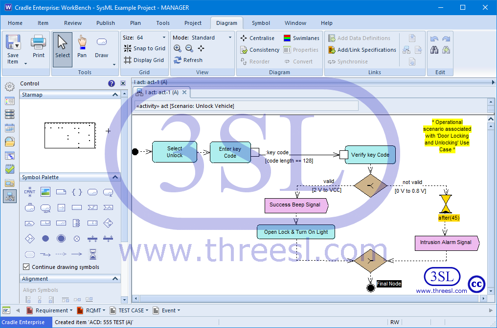
Activity Diagram (act)
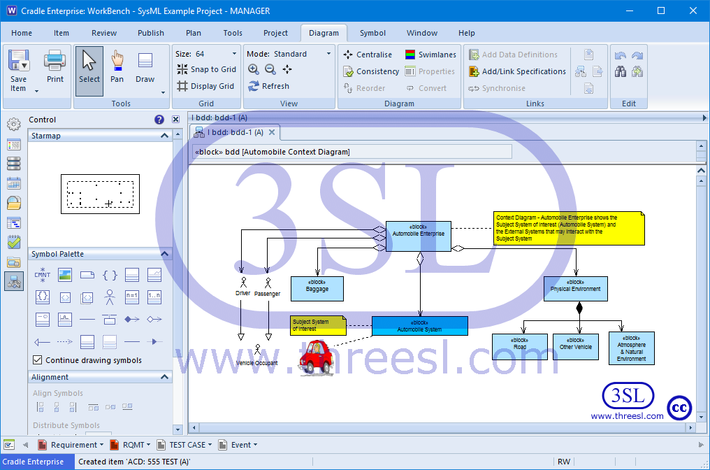
Block Definition Diagram (bdd)
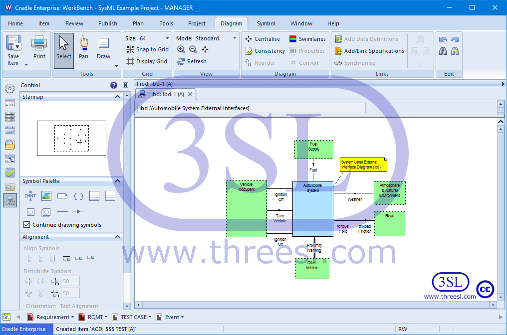
Internal Block Diagram (ibd)
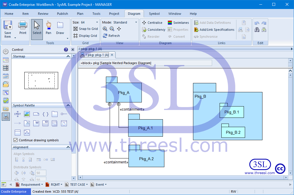
Package Diagram (pkg)
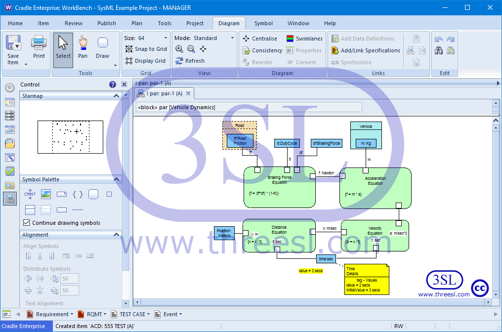
Parametric Diagram (par)
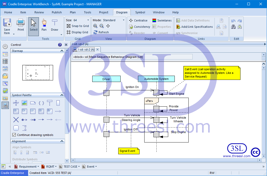
Sequence Diagram (sd)
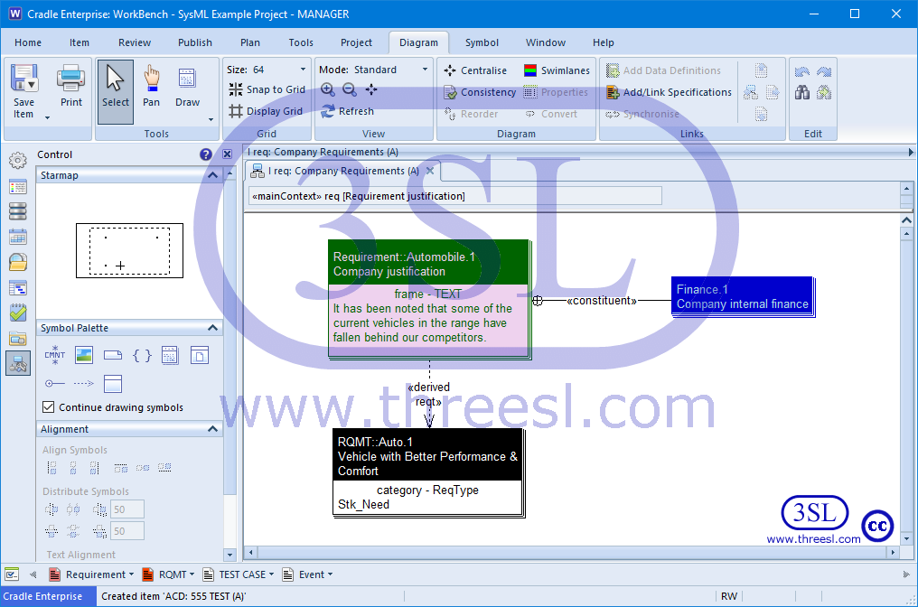
Requirement Diagram (req)
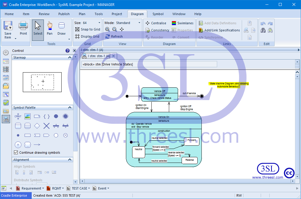
State Machine Diagram (stm)
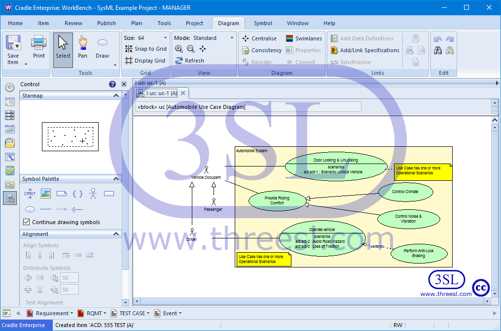
Use Case Diagram (uc)
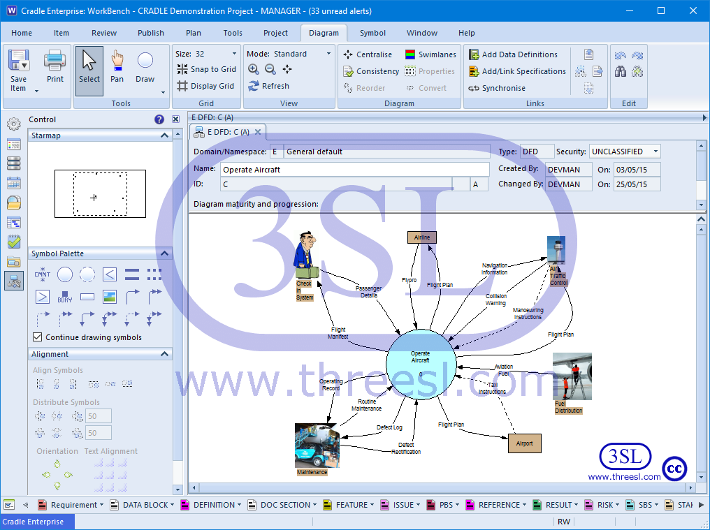
Data Flow Diagrams (DFD)
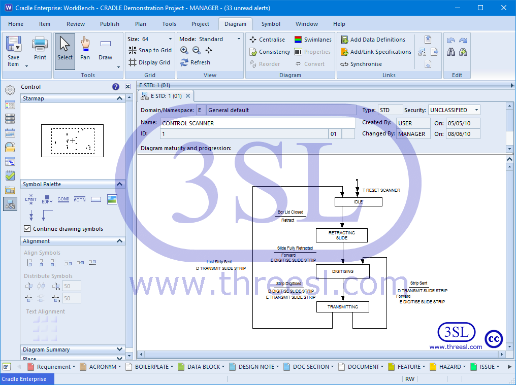
State Transition Diagram (STD)
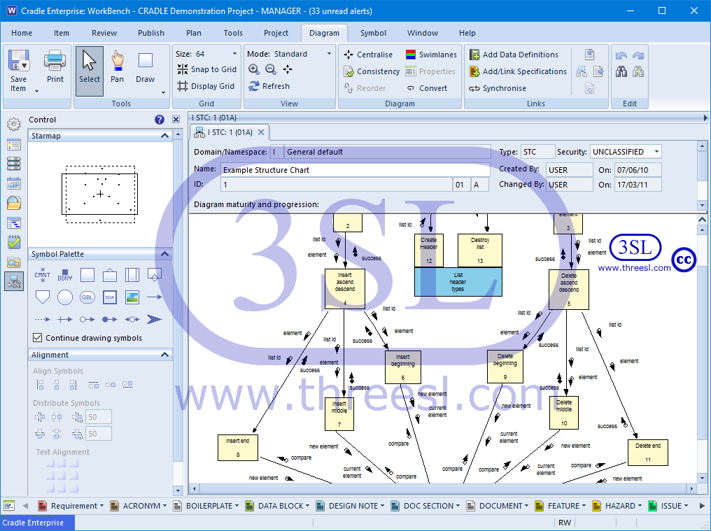
Structure Chart (STC)
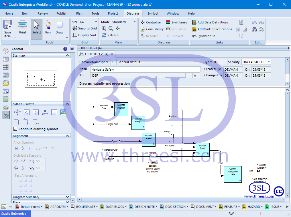
IDEF0
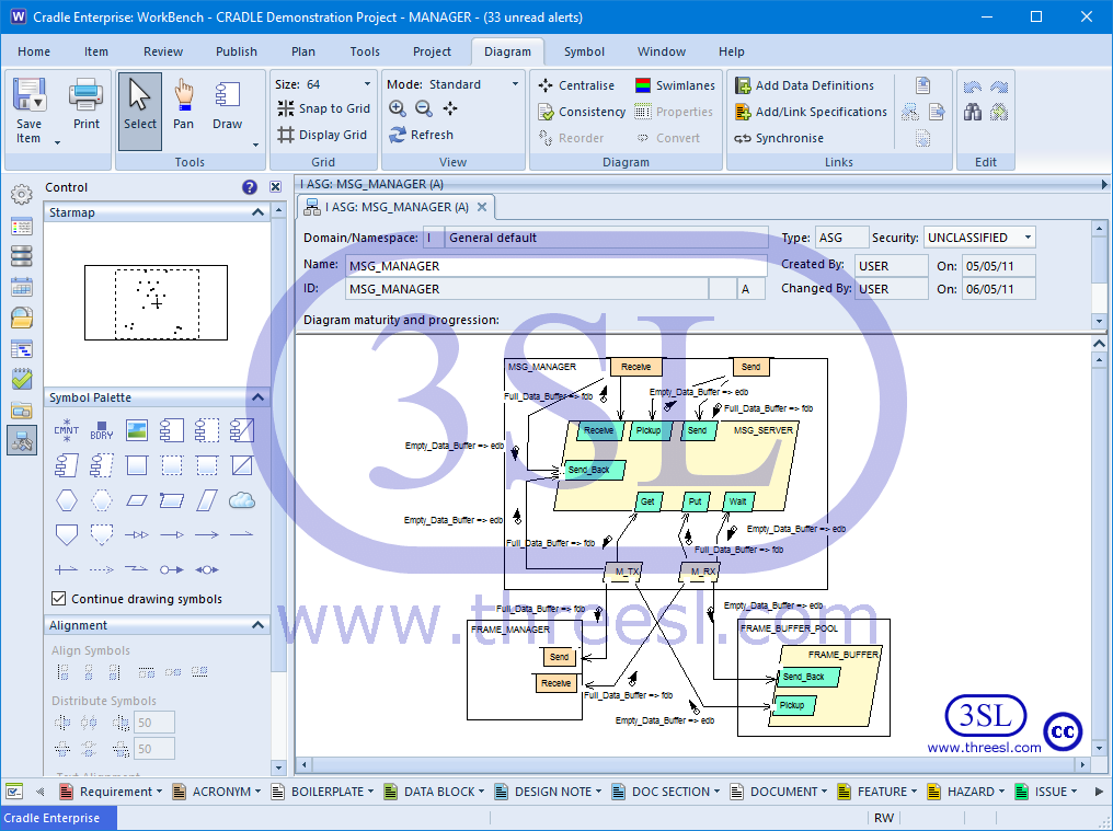
Ada Structure Graph (ASG)
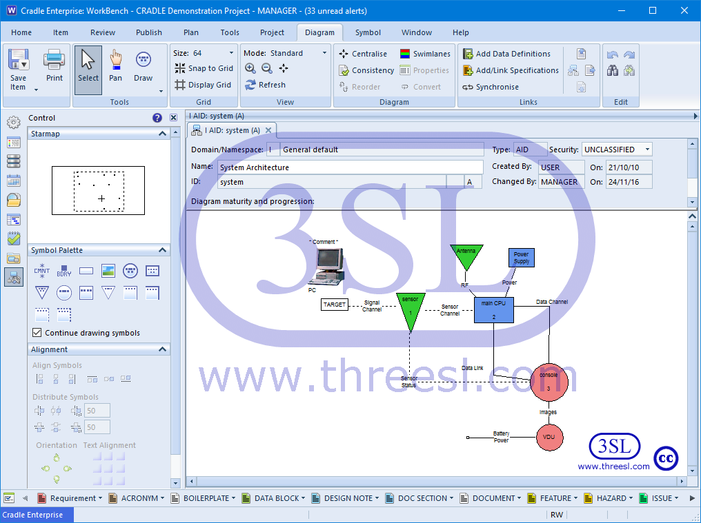
Architecture Interconnect Diagram (AID)
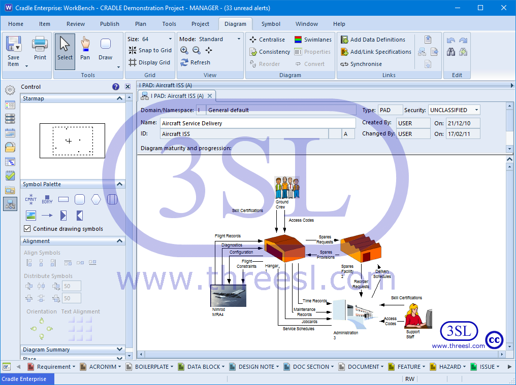
Physical Architecture Diagram (PAD)
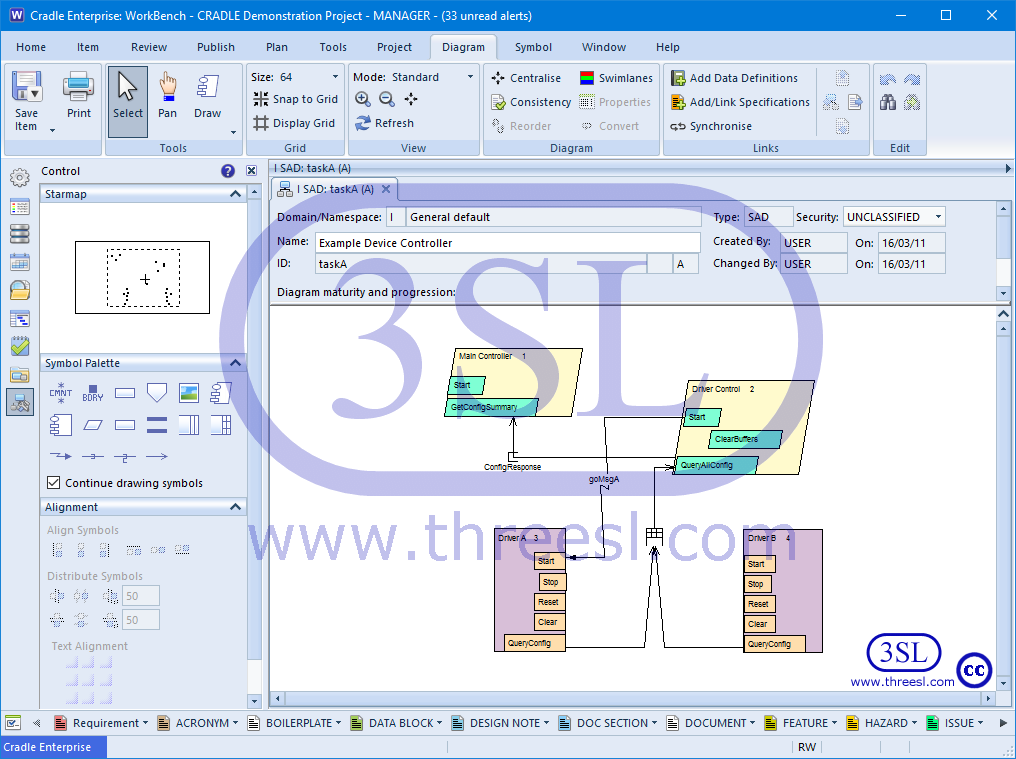
Software Architecture Diagram (SAD)
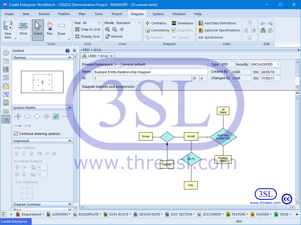
Entity Relationship Diagram (ERD)
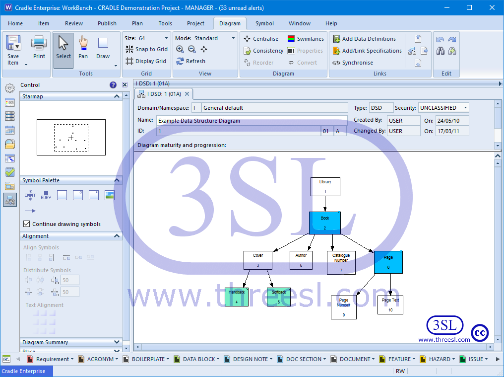
Data Structure Diagram (DSD)
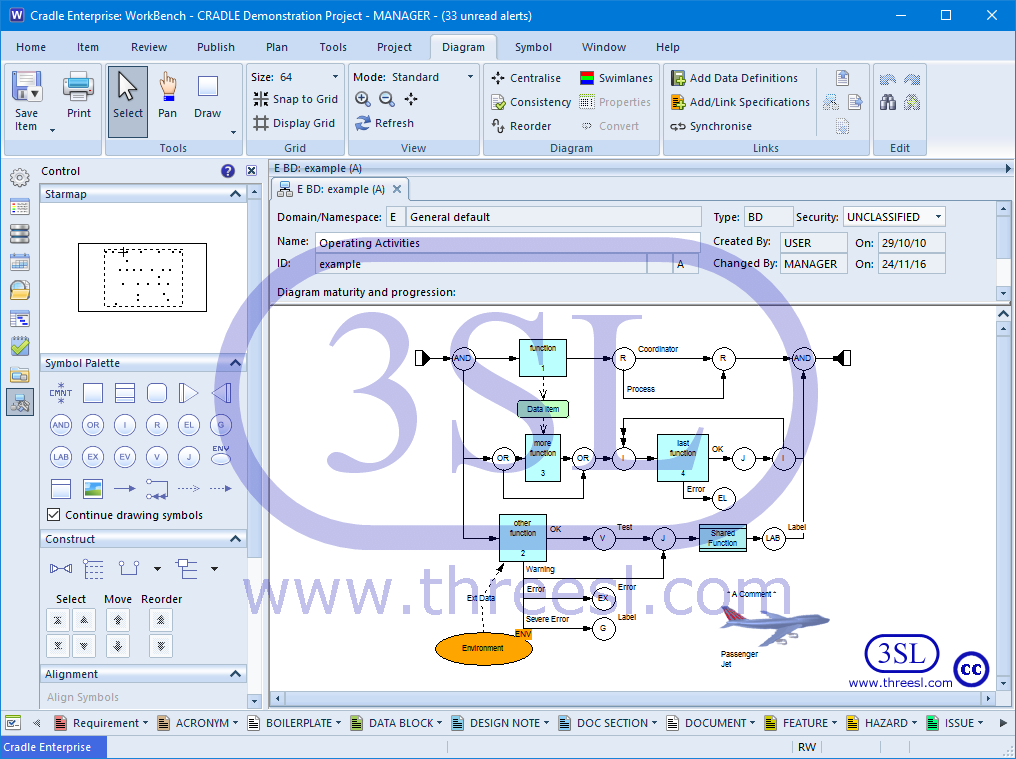
Extended Functional Flow Block Diagram (eFFBD)
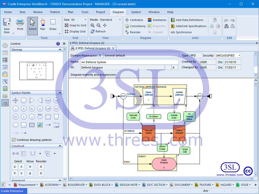
Process Flow Diagram (PFD)
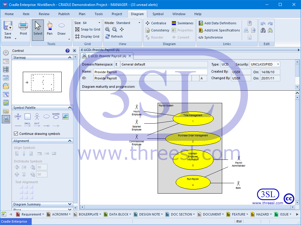
Use Case Diagram (UCD)
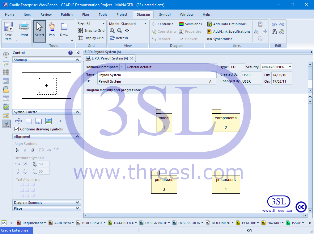
Package Diagram (PD)
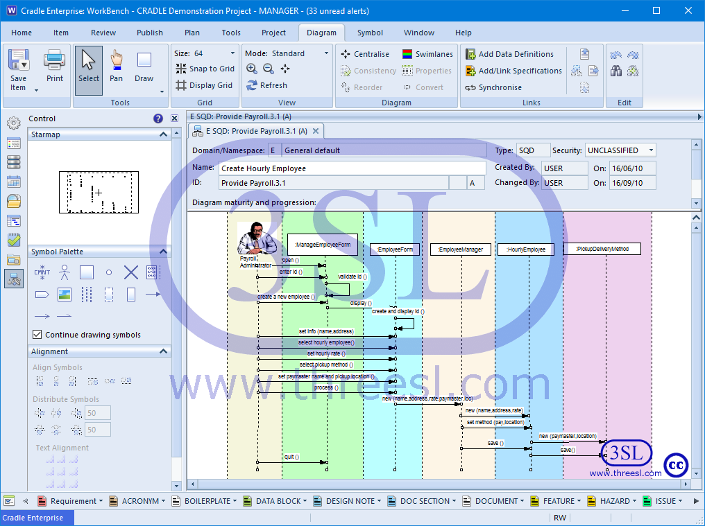
Sequence Diagram (SQD)
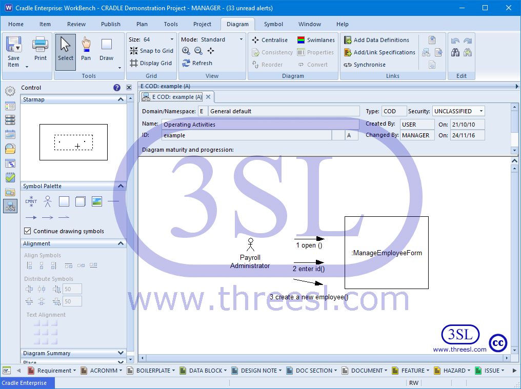
Collaboration Diagram (COD)
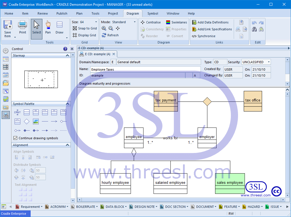
Class Diagram (CD)
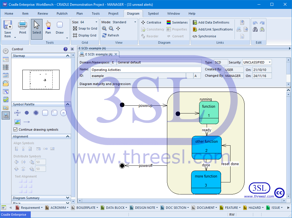
Statechart Diagram (SCD)
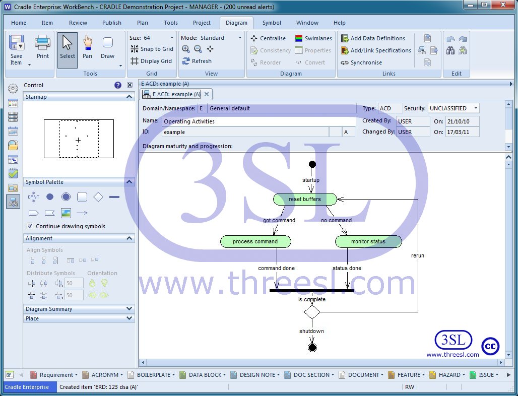
Activity Diagram (ACD)
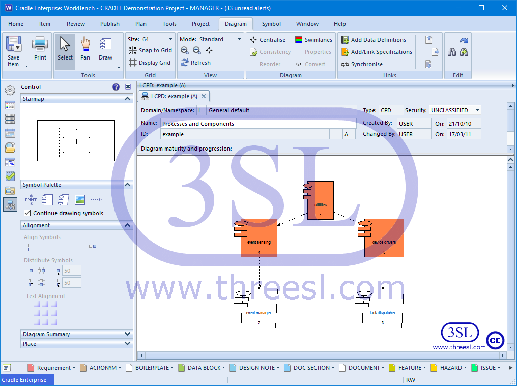
Component Diagram (CPD)
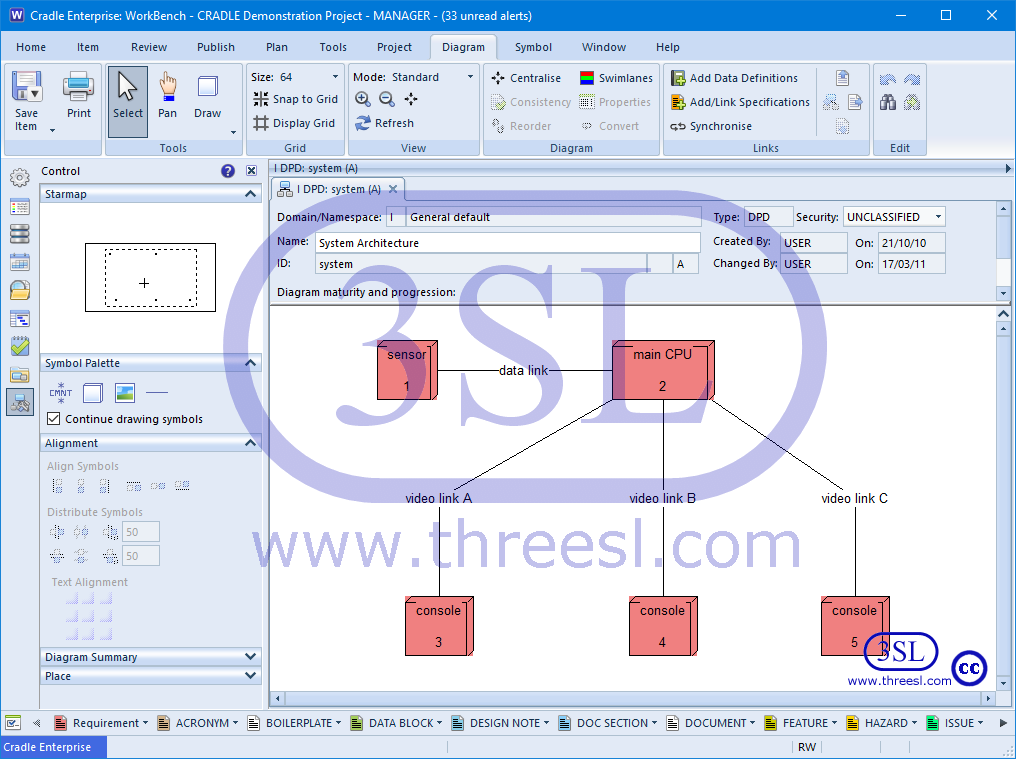
Deployment Diagram (DPD)