Remote Workers and Cradle – Connecting with SSH Tunnels

Your company is using Cradle, but you’re a remote worker – how do you connect to the Cradle server?

If you have the Cradle client utilities installed locally without a local CDS then one method, if you have an externally accessible Linux/Unix system is SSH tunnels.

To use SSH tunnels you need to “lock down” the Cradle server to use specific ports, so they’re not randomly allocated from a wide pool.  You can do this in the $CRADLEHOME/admin/ports file.

Make a note of the internal IP address of the Cradle server – we’ll use CDS_IPADDR later in this post to reference this address. (In this test environment it is 192.168.11.168)

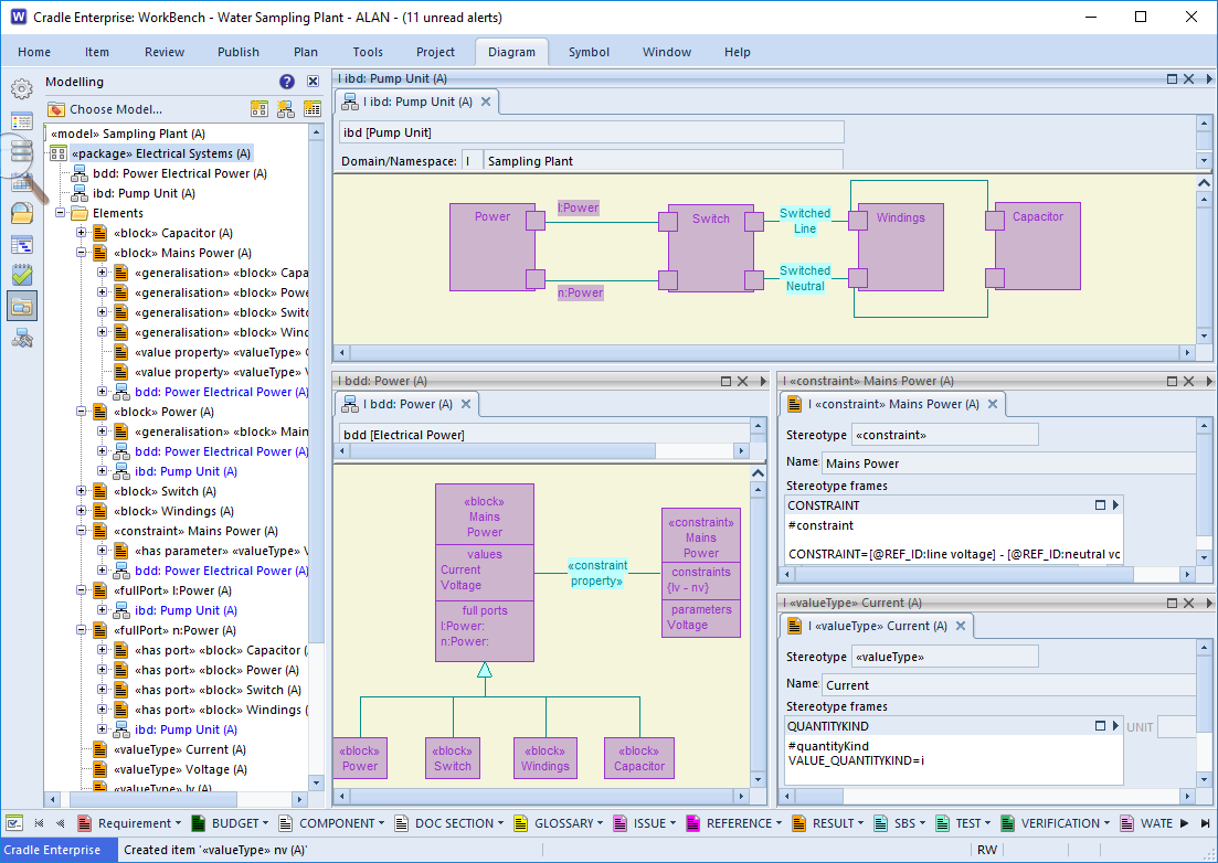
Cradle Configuration Changes

As an example of a small Cradle system with 6 users we can configure the ports file as such. (We’re setting ports for each possible user and an extra)

CDS_UDP_PORT_NUMBER = 23960
TOOL_UDP_PORT_NUMBER = 23961
PRJMAN_UDP_PORT_NUMBER = 23962

CDS_TCP_TOOL_PORT_NUMBER   = 16161
CDS_TCP_PRJMAN_PORT_NUMBER = 16162
UTILITIES_TCP_PORT_NUMBER   = 16163-16169
WBENCH_TCP_PORT_NUMBER      = 16170-16176
CWS_TCP_PORT_NUMBER         = 21211-21217
PRJMAN_TCP_PORT_NUMBER      = 16177

This ports file needs to be copied to all the clients using this CDS.

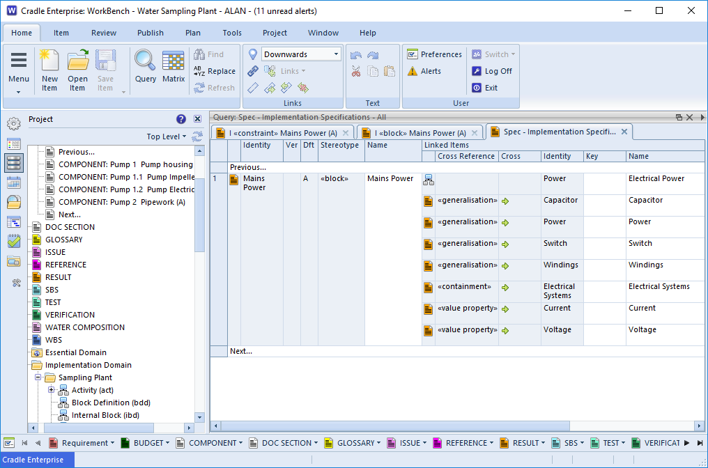
Putty Configuration Changes

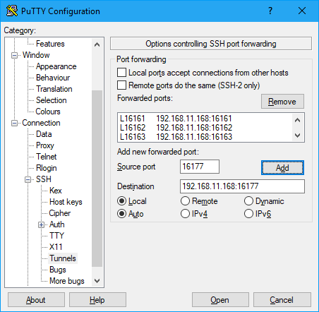
Now we can look at configuring the SSH tunnels. To do this we’ll be using PuTTY – probably the most popular Windows SSH client.

First off, click on the Category Session and enter the hostname or IP of the externally accessible box in the Host Name field.
Now expand the category SSH and click on Tunnels.
For each of the ports configured in Cradle we need to add an entry.
So, for the first one:
Source port  23960
Destination CDS_IPADDR:23960
You can leave the radio buttons alone (set to Local & Auto)
Now click the Add button.

In the Forwarded Ports box you should now have an entry similar to:
L23960     192.168.11.168:23960

Repeat this for all the other ports and we end up with a Forwarded ports section which looks like (if you scroll up and down):

Cradle Putty Tunnel Settings

L23960 192.168.11.168:23960
L23961 192.168.11.168:23961
L23962 192.168.11.168:23962
L16161 192.168.11.168:16161
L16162 192.168.11.168:16162
L16163 192.168.11.168:16163
L16164 192.168.11.168:16164
L16165 192.168.11.168:16165
L16166 192.168.11.168:16166
L16167 192.168.11.168:16167
L16168 192.168.11.168:16168
L16169 192.168.11.168:16169
L16170 192.168.11.168:16170
L16171 192.168.11.168:16171
L16172 192.168.11.168:16172
L16173 192.168.11.168:16173
L16174 192.168.11.168:16174
L16175 192.168.11.168:16175
L16176 192.168.11.168:16176
L16177 192.168.11.168:16177

Click back on the category Session, then add a name to the Saved Sessions and click on Save – so we don’t have to do this again.

If you now click on Open and login to the Linux host.
You can now use your local Cradle client with it pointed to the CDS as being on your local IP.

While you have this SSH session active, you will be able to access the CDS over the SSH tunnels.

Count the Shalls

‘Shall’ Counting

“Count the shalls!” This was one of the strangest introductions to Requirements Management that I’ve heard. Firstly as a young engineer I didn’t know what a ‘shall‘ was, let alone why I should count it. For those of you reading this thinking “… no Idea what he’s on about..” let me explain. A crude method of working out the size of a project requirement was to count the number of paragraphs containing the word ‘shall‘. This gave the number of mandatory contractual statements that must be met for the project. Paragraphs containing ‘should‘ or ‘may‘ could be ignored as they were ‘nice to haves‘ rather than obligations.

counting the shalls as a method of determining contractual requirements
Shalls

Limitations

There is some logic to the approach, if the statements have been written atomically. However, as a provider one should never presume the customer has written the requirements to the right level for ‘shall counting‘.  For example these two customers’s requirement  sets are wildly different.

  1. The vehicle shall carry a load of 500Kg
  2. The vehicle shall pass legal requirements for use on UK roads.

and

  1. The pipe insulation shall be provided in 1m lengths
  2. Insulation shall be installable with standard DIY tools such as a craft knife and tie-wraps, and not require specialist equipment.
  3. The insulation shall achieve a thermal conductivity of  0.033W/mK or lower
  4. The insulation shall pass BS EN11925-2 BL
  5. No component material shall be classed as hazardous to health under COSHH regulations 2002
  6. The wholesale price point shall be 20p / m or lower

On a ‘shall‘ count the first project seems easiest just two requirements. But seriously!  would you accept a customer level requirement like this, and price up the work and expect a happy customer?
Have a Ford Transit, job done.
Then you find the customer wants to crane the load on.  Secondly you find they need a tailgate lift to unload it. Additionally you find the product needs weather protection during transit and so on.

The second project has SMART requirements
S pecific
M easurable
A ttainable
R ealisable
T raceable
Count the shalls here, and the measure may be a little more meaningful.

Shoulds and Mays

Can you afford to ignore ‘shoulds‘ and ‘mays‘ ? Contractually you could argue they don’t matter, but in forming a meaningful customer relationship, they are still important. “The insulation should be a mute colour” could contractually be met with vivid red foam, but you’re unlikely to get repeat business.

When the customer has an idea of the implementation (OK, requirements purists, don’t have a coronary) then they are guiding you as to the options they see as most appropriate.  “The vehicle shall have a mechanism to remove the load at a customer site” could be met with a separate fork lift truck being supplied. However “The vehicle may have a powered tailgate lift, or a body mounted mini crane” suggests the customer is seeing these as preferred solutions. In costing a bid these should certainly be considered. However, if your vehicles come with built in vehicle body to floor conveyors, this could still be a viable solution for the customer. After discussion your system requirement, linked to your customer requirement may become “The vehicle shall be fitted with a 800Kg NWL body/floor conveyor ” Of course this requirement would also have extra data within or linked to it minuting the discussion with the customer where they agreed this would meet their requirement.

Solutions

example of the types of language that should be evaluated automatically
Conformance Checker Settings

There are definitely merits  for someone or something to ‘count the shalls’. If you have 1678 requirements in your project and 1698 ‘shalls‘ you obviously have some non atomic requirements.  Running a Conformance Checker can validate the semantics, across your whole requirement set. What automated tools can’t do is look at the logic and complexity of the requirement. In these cases breaking your customer requirement into a number of domain specific system requirements ensures the level of the requirements against which you bid, design and build are truly SMART. Whilst unsurprisingly we advocate the use of a tool to manage your requirements, to link the User Requirements to the derived or system requirements, we don’t claim a tool will solve the problem of poor specification;  For that you need good, competent engineers, whose job is made easier by using the correct tools.


Building One Brick at a Time

Building your Dream

In the words of Phineas T. Barnum starting with the smallest blocks you can build it “….one brick at a time…”[1] and then you should be able to achieve anything you can dream of.

LEGO bricks based on image from rick mason via unsplash
LEGO® bricks

Consider your ‘dream’ as the top level requirement, this is your ultimate goal. The problem is you’re not sure what constitutes a ‘brick’. Unless it’s a wall you’re building the smallest parts are unlikely to be equal. If only all world engineering problems could be solved with LEGO®! The aim, however is still the same, take the goal and break it down to atomic parts that we can quantify, specify and build. Together those elements will form the whole.

Breakdown Structure

Hierarchies are an important way to describe, link and visualise the ‘dream’ you’re building. The bottom of the hierarchy should be as close to the ‘brick’ as possible. A self contained, unit, the ‘atom’ within your project.

People

Most people are familiar with a company structure from the MD to the process workers via managers and team leaders workers. Imagine a company where every worker tried to talk to the main boss, as soon as there are more than a handful of employees, this would become unmanageable. Conversely consider too many layers of middle management, all pulling in slightly different directions, then the workers end up without clear direction. It’s a balancing act.

Requirement Breakdown

Your ‘dream’ may be to reach for the stars, or it may be to install the machinery to make spaghetti. In both cases you have an end goal, the main top level requirement. In each case these problems can be broken down into smaller problems, launch, travel and land, or ingredients, process and pack.

displaying hierarchies
A Collection of SBS Hierarchies

These in turn may break down into mechanical, electrical and software problems. The decision as to where to break will depend on the industry you are in, the number of issues that need to be tackled and the logical breakdown of the components. In this comparison, the launch may be considered completely different to the travel or landing requirements. However, in the factory system, it may be more prudent to devolve the level directly into the mechanical and electrical areas as there may be no significant difference between process and packing. Falling out the bottom the atomic ‘bricks’  may now be motors, control sensors, and pipes.

Realistically a more complex project can consider in parallel with the ‘dream’ or ‘User Requirements’, that there are the ‘System Requirements‘ which possibly lead to ‘Derived Requirements‘. These in turn  link to the ‘System Breakdown Structure‘ (SBS) and  ‘Product Breakdown Structure’ (PBS) .


Work Breakdown

Image showing the project plans process
Project plans process

When the problem has been broken down into the smallest conceptual parts the order that these must be assembled can also be broken into a hierarchy. The mechanical systems must be installed before they can be wired, the control systems may be developed in parallel, but they can’t be integration tested until the sensors are installed. A work breakdown structure (WBS) is a plan to ensure that the right bricks are in place at the right time to support the next layer of the structure.

Dependencies

the interrelationship between parts of the project's design and components
Complex Project Dependencies

There will be a complex relationship between each of the hierarchies in your project. If your team of electrical engineers are required to complete two different parts of the WBS they can’t be completed in parallel. This is where plan schedules are useful. Microsoft® Project is one way to achieve a schedule using Gantt Charts to illustrate the sequencing. The links between which System Requirement links to an item in the SBS or which Derived Requirement links to a PBS item must also be maintained.

Tools

Therefore, to manage a  big problem it needs to be broken down into smaller atomic ‘bricks’. But the interrelationship of those components is complex and needs to be managed.  Cradle allows all these components to be managed, linked, visualised and reported.  From whatever your original concept, to the final brilliant creation, you can build it one brick at a time.


1.  Lyrics ‘Barnum’ by Michael Stewart.

What is a System?

System

[sis-tuh m]noun:  an assemblage or combination of things, parts, sub systems, members, operations or principles forming a complex or unitary whole.

Context

To answer the question ‘What is a System?’ you first need to understand your context. When you get down to the ‘atomic’ level for your component parts you’re unlikely to model them any further. A local authority may want to model their transport system. This may include vehicles, termini, and ticketing systems. Whilst their model may include the external specifications of a bus (in terms of weight and width) to plan a terminal, they are unlikely to care whether the bus electrical operates on 24v or 48v batteries.  Unless they have to supply charging points at the depots. The tram’s external specification would again include width, height and mass, but it is very likely that the authority would need to know the electrical operation characteristics in their model if they are responsible for the track.

illustration of systems and context
System Components

The bus manufacturer is not really interested in how the local authority terminal looks or operates. However, they may have design constraints for the width or length imposed by their customer. Being able to identify these parameters in their design will help them design any modifications needed to meet the requirements. Some times there is need for shared information. The ticketing system may be supplied by a third party, both the council and the bus vendor will be interested as part of that system will fall within their responsibility. Ticket sales at the terminal, ticket machines fitted on the bus. The bus manufacturer will undoubtedly model their vehicle, there will be detail plans of what connects to what and what operational parameters are needed for each. In this way if a new component is introduced, it is easier to see the impact. The new air conditioning unit needs 48v supply, the bus currently uses 24v how do we assess the impact and know what is dependent on the current voltage line?

Should I model X?

Whether a system, or sub-system is worth modelling heavily depends on your position in the project chain. Deciding whether this is ‘atomic’ level for you is very dependent on your industry. Assessment should be made as to  the likelihood that parameters of the component may affect higher level systems. The likelihood of whether a subsystem is going to be re-used in a number of different high level systems, and whether stakeholder or external constraints need to be considered.

modelled low level components
Circuit model

If you make capacitors, you’ll have specifications for the capacitor, it’s voltage, capacitance, temperature range and so on. However, there is not much you can model at this level. If you also make wire wound inductors, then it will have similar specifications. However, as soon as they are linked together forming an LC oscillator, you have a system. There are two components who’s characteristics interact. If the LC sub-system is being supplied then the voltage at which it is safe to operate will be dictated by the components within. In this case specifying the inductor and capacitor as blocks with characteristics that form the internals of the oscillator will have a benefit in future design or specifying the operation of the sub-assembly supplied to onward customers. As the vehicle parts designer wanting to make a turning indicator unit, whether the oscillator is LC, RC and Transistor or Op-Amp is of little concern as long as the voltage, current and timing are correct. The oscillator would therefore be the atomic level here. The bus designer is not worried about the indicator unit design as long as the brightness and timing meet regulations and the longevity and power consumption are within performance parameters. They would have no interest in modelling the oscillator.

Model Benefits

Query showing relationships
Linked Specification

The fact that your model contains detailed information of the interconnections, parameters and ranges of your atomic components makes querying your model to analyse change much easier. Being able to identify all components that are expecting the same power will aid a designer in assessing the impact or running a different voltage.

Can you model anything?

Pretty much any system can be modelled. Software was maybe the original stable from which many modelling techniques originated, there is a need to define at what point each module interacts with the other modules. The depth to which the functions are modelled will again depend on the context. There would be no point modelling the printer driver in the system beyond the interface, if that driver is purchased along with the printer hardware. Library functions may be modelled in their own right, but the higher level designer will reference them as white or black boxes.

No one model has to contain everything. The passenger movements, purchases modelled as use cases. The hardware components forming the bus. The sub components forming the indicators. The software controlling the ticket system are all separate systems working as a whole.


Baselines – The end of the road in Configuration Management?

End?, No Way! A Baseline is just the beginning……

Divide and conquer bound, line in the sand
Clichés

When you have a complex problem, it is always good to ‘set some bounds’1, ‘divide and conquer’2 and ‘place a line in the sand’3. That’s 3 so far on the cliché count, but they are all true reflections of baselines and configuration management processes.

Baselines and Configuration Management. No real life project is static, it never has all the answers available up front and even the most basic of tasks is likely to have a change to its requirements. Changes can range from an alteration of delivery date or change of colour, to a whole change in direction caused by a change in circumstances, finance or regulation. If we’re not careful, project managing this changing landscape4 the ever changing goal posts5 puts project completion at risk.

We need to be clear that the proposed system requirements matched up to the user requirements at a particular point in time. Recording a baseline is that proverbial ‘line in the sand’. A baseline records the conditions at a point in time. The initial user requirements right at the beginning of the project would make an ideal baseline. It gives us a foundation to work from6. From there we can record, measure and control how the project develops. Far from being the ‘End’ of a project lifecycle, a baseline is a really good beginning.

Point of Decision

Now that we have our foundation, we can decide whether it is solid enough to build on. At present it may be more akin to a trench with some hardcore in the bottom, and nothing ready for a wall. However, we can now discuss these baselined requirements/or characteristics before moving on.

A Trench excavation at Winterbrook Oxfordshire - Bill Nicholls [CC BY-SA 2.0 (https://creativecommons.org/licenses/by-sa/2.0)], via Wikimedia Commons
Foundations
“Is the wall definitely in the right direction?”,  “Is the wall to terminate at the end of the garden and no further?” (Setting the bounds) “Are you happy for us to quote for the full wall on this basis, or do we need to set a half-way house7 at the first course and then re-evaluate?” (Divided and hopefully conquered).

If all is well we can specify the system requirements and get the concrete poured. This firming up of the foundations8 would be another good baseline point.

Managing Change

“The neighbours have complained, the wall is too short to keep the dog in”.  Back to the drawing board? Not quite, we can go back to the baseline and check what the agreed characteristics of the foundations were. We can’t build the wall higher in solid blocks as the  foundations were not laid with sufficient margin for the extra weight. However, building the top part of the wall in decorative open block-work will meet the changed requirement and satisfy the user. Costs adjusted, new quantities calculated and time to take a new baseline.

Whilst ideally the project would have been planned from start to finish, before the first components were laid, this is not always possible or practical in real life. Recording when and why changes were made will help us make decisions based on firm ground9, rather than walking on sinking sand10.

bricks, wall garden
Garden Wall

Far from being end points, baselines should be seen as stepping stones to your goal11. However, they should not be seen as a linear path. There may be more than one path across the river12, and not all routes will lead successfully to the other side. Assume the neighbour decides to move and takes their dog with them. We can rewind to the baseline taken at the foundation stage and progress down the original planned height in solid bricks as we have the record that this was a possible solution at that point in time12.

Baselines and Configuration Management (CM)

CM is a process that aims to establish and maintain the quality and consistency of a system’s performance, functional, and physical attributes throughout its life. It is tightly linked to the Quality Management System (QMS) and Requirements Management System (RM/REQM) employed on a project. Deciding when and whether items should be baselined, would generally be subject to review (QMS). Providing traceability through the project’s lifecycle also a QMS function. Gathering, eliciting, and decomposing requirements is an RM function. Dealing with change, would need elements of all three. Whilst it may be fun playing cliché bingo, it really is time to place a stake in the ground13 and record milestones in your project14. Don’t delay baseline TODAY!

A Holistic View – The Context Diagram

Context Diagram – the world around our project

A context diagram aids visualisation of where a project sits in relation to its external interactions. We don’t want to model those external systems, but we do want to know how they interact with our system.

Automatic wipers for a car don’t need to know how the weather works, but they do need to sense the presence of water on the windscreen. The context would, therefore, include the weather as an external influence with ‘rain’ or ‘rain present’ being signalled to our system. If our company only produces the wiper element the actual car is outside our scope. However, this is where we get our power from and it’s where we will install them so the car is part of our context. The interactions with the car such as ’12v supply’ and ‘user control signal’ are likely to show a part of the holistic context.

Data Flow Diagram (DFD)

In terms of functional analysis and design the DFD shows the external elements with which our main system interacts on the context diagram. This usually has only one process on it, and that is our system of interest.

an example context diagram
Context Diagram – DFD

Taken from the Cradle demonstration project this diagram shows our system of interest is operating the aircraft. The externals that we interact with form the context within which the project operates. This includes the booking system, the fuel suppliers, the control tower and so on.

When the design and analysis are broken down at lower levels, the passenger details or navigation information will have to be handled by parts of the target system. If there is anything that does not balance at the lower levels, then a function must be missing. It implies that we have an input stimulus or an expected output and have nothing to handle or provide it.

Block Definition Diagram (bdd)

Context diagram notations are not restricted to Yourdon, a SysML bdd is also used to describe the context. Information gathered from the use cases and operational scenarios can be used to build a holistic view.

Context diagram shown on a bdd
Context Diagram – bdd

Visual

Whilst not necessary, adding images to your context can aid communication to your stakeholders and customers. They don’t really have to understand the notation to visualise the ‘Passenger’ as a person interacting with the flight. In Cradle, images can be added to the diagram as standalone images, or can actually replace the symbol on the diagram. (The image in the latter will follow all the rules and have the underlying specification of the real diagram element).

The 4 Types of Requirement Confirmation

Every user requirement must be a clearly stated expressions of a stakeholder need for an externally-observable characteristic of the system being developed. Therefore, it must be possible to check that the system we have built satisfies all of its user requirements. Since there are different ways to check things, it is helpful to identify the 4 types of requirement confirmation and to tag all requirements with one or more of these types as early as possible in their development.

the 4 types of requirement confirmation
Verification and Validation in the Systems Lifecycle

Verification and Validation

But first, we need to define some terminology. The terms verification, validation and the acronym V&V are often used for checking compliance with requirements. Sometimes they are used differently, which can be confusing. So, we will define them first:

  • Verification is the activity of checking that the implementation, build or construction of a component, and the system itself, has been done properly. It is the idea of checking that a power outlet has been wired correctly and that it is properly earthed. Verification means to answer the question “have we built it correctly?”.
  • This is a good question to ask, but it does not answer the question “have we built the correct thing?”. That is validation. So, validation means to check that the system conforms to what its stakeholders asked for.
  • V&V is the combination of these two. Depending on your preference, it could mean either Verification and Validation, or Validation and Verification. Most of us in 3SL prefer the second, as it is a little easier to say. The two are equivalent. As a result, V&V simply means to check everything, from the quality of the raw materials, and the fabrication or assembly of components, to the final inspection, configuration, alignment or calibration of the finished product.

The 4 Types of Requirement Confirmation

The 4 types of requirement confirmation are:

  • Inspection, or I
  • Analysis, or A
  • Demonstration, or D
  • Test, or T

We usually abbreviate these types to IADT. They are often called validation methods.

Most requirements will have one of these validation methods, but sometimes a requirement will have more than one.

The Requirements Confirmation Methods

We can describe the 4 types of requirement confirmation as follows.

Inspection

Inspection is the examination of the product or system using basic senses. This means to do one or more of look at it, touch it, smell it (rarely applicable), taste it (even more rarely applicable!). So, we would physically examine a product and check that all its physical characteristics are as required and that it has all of the controls that it is supposed to have. Similarly, for a software system, we would check that its UI is as required, that it has all of the data entry fields and buttons that it is supposed to have. For a web application, we would check its appearance on different screen sizes.

Analysis

Analysis is the validation of a product or system using calculations and models. We will use analysis to make predictions of the product or system’s performance based on some representative, actual, test results. We can use analysis to calculate failure points based on actual test results, without resorting to destructive testing (expensive as we can only do it once!).

Demonstration

Demonstration means that we use the product or system as it is intended to be used. So we can follow the functional user requirements and check that the product or system does what the user requirements say that it should do. We will press every button and use every control in a product to confirm that the product does what it is supposed to do. For software, we enter data as users will do and ensure that the software performs the actions that it is supposed to do and check that its reports are correct.

Test

Test is a more precise and controlled form of demonstration. We test a product to confirm that it behaves precisely as specified under a set of carefully specified test conditions. We repeat these operations using different sets of test conditions, following precisely-specified steps to complete the test. Therefore, this is often to verify performance requirements.

Use in the Process

It is good practice to specify the confirmation criteria for each requirement as it is written. This is because it helps reviewers to confirm that the requirement has been written clearly, by answering questions such as “could I inspect the product and confirm this requirement?”, or “could I demonstrate that this requirement has been met with the finished product?”, and so on.

Once the requirement and its confirmation method(s) are agreed, we can create its confirmation item(s). If a requirement is simple, then it will have one confirmation. If complex, we will create more than one confirmation.

Similarly, if the requirement has multiple confirmation methods, then we will need a confirmation item for each of them.

Therefore, the goal would be a single validation for each requirement, because an atomic requirement (one that says only one thing) should only need one validation.

Of course, both user requirements and system requirements will have a confirmation method. So we would normally talk about validations and verifications, and not the more general term, confirmations. Therefore, we would refer to:

  • The validation method of each user requirement
  • Writing validation items for user requirements
  • The verification method of each system requirement
  • Writing verification items for system requirements

Although it is impossible to generalise:

  • The confirmation methods of user requirements are predominately Inspection and Demonstration
  • The confirmation methods of system requirements are predominately Test and Analysis

Functional and Non-Functional Requirements

A Requirement that works and one that doesn’t?

Grammatically the difference between the types of requirement could be seen like that, but not so in RM (Requirements Management) parlance. Functional and Non-Functional Requirements are a what and how of engineering.

HID showing how functional and non-functional requirements link to form the overall set
Interlinked Functional and Non-Functional Requirements

Functional Requirement

These define what the features are. “The User Interface board shall send an enable signal when the user presses the On key”
or “The finance reporting mechanism shall produce a summary report automatically at the end of each month”. These requirements tell the designer/implementer what the systems need to do. They can be read and agreed by the customer and will align with their expectations of the system.

Functional requirements are not limited to actions. They can include regulatory or safety requirements, “The system shall be protected and able to be certified to IP44”, or internal rules “The output format shall be commensurate with detail explained in the operating procedures for the production line”. They can reference other external requirements or standards. “The electrical interface shall be compatible with USB 2.0 standards using type A connectors, verified by a third party.”

Non-Functional Requirement

These define how the system will operate. They will place constraints and capacities on the system that can be measured.  “The User Interface  enable signal shall be a TTL level present within 0.25 seconds of the user making contact with the physical interface” or “The finance reporting mechanism shall be capable of summarising 100K entries into the 10 specified categories”.

These limits and descriptions provide bounds within which the Functional Requirements can me met. “The system shall allow users to cross the road safely” is a wide Functional Requirement. “The user shall not need to interact directly with the facility”, “The design shall comprise of a fixed physical system requiring no power”. Looks like we’re building a bridge or subway rather than a pelican crossing then!

Lines are Drawn

There is always going to be a grey line between the two areas. Some will depend where the responsibilities end and so on one project what is deemed a functional requirement. “The interface must be USB 2.0”, is a main operating characteristic that our system can not change and is needed to interface to an external system. On another project the functional requirement may be “The main system should interface with up to three external input and output devices” and the design team may decide “All inter product interfaces shall use USB 2.0 standard communications”

In the ideal world everything should operate 100% of the time without failure and should be completely intuitive. Should occur without delay and should be fixable for ever. However, the world we live in is not ideal. System designers need to recognise that. Non-Functional Requirements can define these limits and manage expectations, from both a contractual and measurable quality point of view.

  • “To aid the user to perform the task consistently. The UI shall provide guidance in the form of fixed text and sequenced indicators.”,
  • The system shall have an availability no less than 99% of the time”, 
  • “Visual and audible feedback shall be provided within 0.2 seconds of any interaction”,
  • “Design components should have an availability before EoL of two years minimum”

For every system these user experience, reliability, performance criteria, and through lifecycle considerations should be made.

Remote Workers and Cradle – how do they communicate?

Cradle, like many modern applications, uses networked communications between clients and servers. However, with modern working practices, often not all users are on the same site. Some, not even the same continent as the Cradle server. So we need to create a method to allow these remote workers access to the Cradle server.

Thin Clients

3SL created the CWS (Cradle Web Server).  This allows a capable thin client deployment to local and remote workers without the need to install Cradle WorkBench.  But some customers want their remote workers to have access to the full capabilities of WorkBench, Project Manager, Document Publisher, and Document Loader; so how can these remote workers deploy the Cradle clients with network access to the server?

Virtualised Applications and Desktops – (e.g. XenApp, RemoteApp)

Citrix XenApp® and Microsoft® RemoteApp allow your applications and desktops to be virtualised and then served to the user from central servers.  The Cradle client utilities are installed on the Application Servers.  Users are able to connect to the server which redirects the Application or Desktop display to the users device.  These technologies allow users with devices which are not currently supported by 3SL to use the full desktop Cradle applications.

Many Cradle customers use Citrix XenApp® and Microsoft® RemoteApp virtualised apps and desktops to serve Cradle WorkBench, and other Cradle utilities to their local and remote workers.  But what if you’re remote and your company doesn’t use these distribution technologies? What are your options for remotely connecting to a Cradle server?

There are a number of methods which we have assisted customers in deploying to allow their remote workers access to a central Cradle system.

VPN – Virtual Private Network

Virtual private networks provide a link from the remote hosts to the network where the CDS lives and we can talk directly to the CDS over this connection. VPN can provide host to network, and network to network communications. Authenticating and encrypting VPN links provide security over the internet.

This is the preferred method between sites, or dedicated remote workers, as most customers already have VPN technologies in place and this provides the least restrictions and requires little additional configuration of the Cradle server.

NAT – Network Address Translation

This is where we remap one IP address space to another IP address space.  What this gives us is the ability of a gateway or firewall to route Cradle communications to a CDS behind the firewall.  This can expose the Cradle server to unwanted external traffic if the firewall rules are not carefully locked down.

SSH Tunnels  – Secure Shell for Unix and Linux hosts

Part of this protocol is the ability to map local IP ports to remote IP hosts and ports beyond the remote SSH host. We can use this to direct Cradle communications to the CDS.

You may not wish to expose the Cradle server using NAT as it can open it up to potential hostile traffic, but you don’t want to go down the route of a full VPN solution.  SSH tunnels fulfils this need.

In future blogs, we’ll be going through some of these options in more detail for Cradle specific installations.

Could Do Better?

To the parents of…….

First reports of the new School year are landing on parent’s laps up and down the country. How have their little prodigies settled into their new class, how are they doing with new subjects? Will the envelope contain a list of ‘Could Do Better‘ or will it be a list of ‘ Excellent Effort

As a parent you always hope that the report will be positive, but what do you do about the negatives? How do you better support your child at school?

5 Out of 7 Subjects Great, 2 Need improvement.

School report based oin unsplash.com tamarcusbrown
Report

Ok, so as a parent we know Geography is lacking, but where. Is it a lack of understanding or a lack of world experience or bad handwriting. We could watch some BBC BiteSize revision clips take a world cruise, or get the lined paper and practice cursive fonts. The feedback lacks a little.

B2B Engagement

3SL are generally in the Business to Business market. We want to form a relationship with our customers more akin to the partnership between  parents and teachers than that of a Crisps* manufacturer selling to the mass millions and offering a chance to feedback via a popup on their website. The incentive in this case may be the year’s supply of ‘Cheese and Onion‘ but the quality of the feedback is likely to be limited to my thoughts on whether 6 or 8 packets is ideal as the size of a in a multi-pack or whether I rate the ‘Beef Goulash – special edition‘ higher or lower than my regular ‘Ready Salted

(* Crisps: en; Thin slices of potato fried until crunchy and crisp, en_US; known as potato chips)

Let’s Do a Survey

Surveys definitely have their place. They define a set of measurable criteria against which the business wishes to perform. “All posted correspondence must be dealt with within 14 days” is a laudable criterion, you can ask your customers if they received their mail within
7◘  14◘  21◘  longer◘  N/A◘ days.

"Survey" based on pexels.com/pixbay.com image
Survey

However, this is not much use if the main mail is simply the invoice sent to the company’s finance department. The users of the product, were really more bothered about their email to support being answered promptly, as the project was on the critical path.

Let’s Wait and See

“Businesses will tell us when we’re doing well” right? Generally, wrong!

B2B or B2C will regularly tell you when something is wrong, but far less frequently tell you when something is right. It’s just the way we are. You finish a meal in a restaurant and it was OK you up and leave, you enjoyed it you may leave a tip, you hated it and though the service was awful you may write and complain. (If you’re British you’ll probably say “tut tut, not going there again” but that’s a cultural issue!)

Ask….

If the waiting staff see you are finished and approach your table and ask “Was everything OK? Did you enjoy your meal?” They may well get a range of responses from “Fine” to “Great evening” to “The steak sauce was superb, I hope it’s on the specials again soon“. From this the business can glean more about how well they are doing. You wouldn’t want your waiter to sit down with you and ask if there were areas you felt were lacking and how they could better serve you next time. (It would somewhat ruin an evening). On the other hand getting feedback from that teacher about where improvements could be made, asking what they could do to assist and what you could do to support is a vital way to improve achievements.

Help Us to Help You

3SL are asking.

We want to build that relationship and make Structured Software Systems Ltd, the company you want to deal with. We want to understand how we can better support you.

And the Survey Said…

We know we can answer the phone within a minute (during UK office hours), we know we can respond to emails within the service level agreement. But what we don’t know is whether these are the most important aspects that you value. We can ask Google how fast our pages load, but it may be a piece of vital content that you rate more highly.
So the survey says NO we’re not going to restrain you to a set of tick boxes. We know different customers value different aspects and we want to be able to respond to all those things. We are, therefore, throwing the ball into your court, asking you to provide us with a virtual “parent’s evening” to raise your concerns (or lavish your praise) on us, as the parents, of Cradle.

Get in touch…

social-customer@threesl.com, call us +44 (0)1229 838867 DM us @threesl or post a letter Suite2, 22a Duke Street, Barrow-in-Furness, Cumbria, LA14 1HH U.K (and we’ll try and respond within 14 days!). Tell us what you want, what you rate well and where we ‘Could Do Better’

3rd Party Review Sites

We are also keen for you to provide public feedback at Capterra or TrustRadius which can help others decide on the value of Cradle. Obviously if you have a problem we’d welcome you contacting us first so we can help resolve it, that will benefit you , us and the rest of our customer base.

Further reading:

This article from TrustRadius for vendors is quite insightful  The Engagement Economy: How to build the relationship B2B buyers want

UPDATE: September 2020 – 3rd Party Reviews